Have you ever read an amplifier review and been overwhelmed by technical jargon? How about ad copy that packed in esoteric terminology like the barker at a sideshow? A string of words like discrete direct-coupled single-ended Class A without feedback might seem calculated to dazzle average consumers into a state of shopping compliance, but there’s real engineering behind it. Besides, this is Headphonesty and we’re above average here, aren’t we? This Amplifier Architecture Primer is written to give you the basic conceptual understanding you need to follow the technical discussion that often seeps into reviews and amplifier marketing materials. Each section highlights a common technical term or family of terms, and includes a light working-knowledge explanation, some general ways that it may impact the sound signature or other aspect of a design, and a specific product example illustrating the concept.
Structural Circuits
Amplifiers are divided at the most fundamental level into two groups: These terms describe how a signal flows through and is amplified by a circuit. In a single-ended amplifier, the signal is amplified as a whole from input to output. A push-pull amplifier, on the other hand, amplifies the signal as two mirror images and combines them at the output.
Single-ended
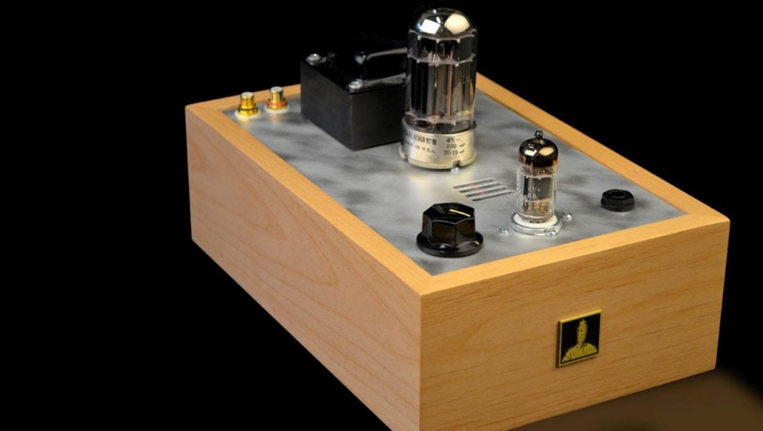
Single-ended amplifiers can be extremely simple, potentially using just a single tube or transistor as an amplifying device. For this reason, single-ended amplification seems to attract designers who follow a ‘less is more’ philosophy. While a single-ended amplifier will tend to produce more harmonic distortion than a push-pull amplifier, it is often of the monotonically decaying harmonic flavor. This is a fancy way of saying it is inoffensive or even pleasing to the ear. In a single-ended amplifier, the devices must each be able to handle the entire signal as a whole. This leads to larger voltages and more current per device for the same output power. In other words, single ended amplifiers are less efficient than push-pull amplifiers. The theoretical limit is 25% efficiency. Because of this, you don’t often find true single-ended amplification in a portable, battery-powered format. The well-known Bottlehead Crack, a DIY darling, is a perfect example of single-ended amplification in a desktop format. Sold in a kit that anyone with a soldering iron can build, the Crack epitomizes the simplicity of this style amp. Many users describe a sweet and organic sound, perhaps a result of the monotonically decaying harmonics common to single-ended amplifier design.
Push-pull
Where more power or efficiency is required, push-pull amplifiers use pairs of devices to amplify mirror images of a signal and recombine them at the output. When compared to holistic single-ended amplification, splitting a signal and stitching it back together sounds like a destructive and potentially lossy process. Reality, however, is closer to the difference between one lumberjack and a saw and two lumberjacks on each end of a saw working together.
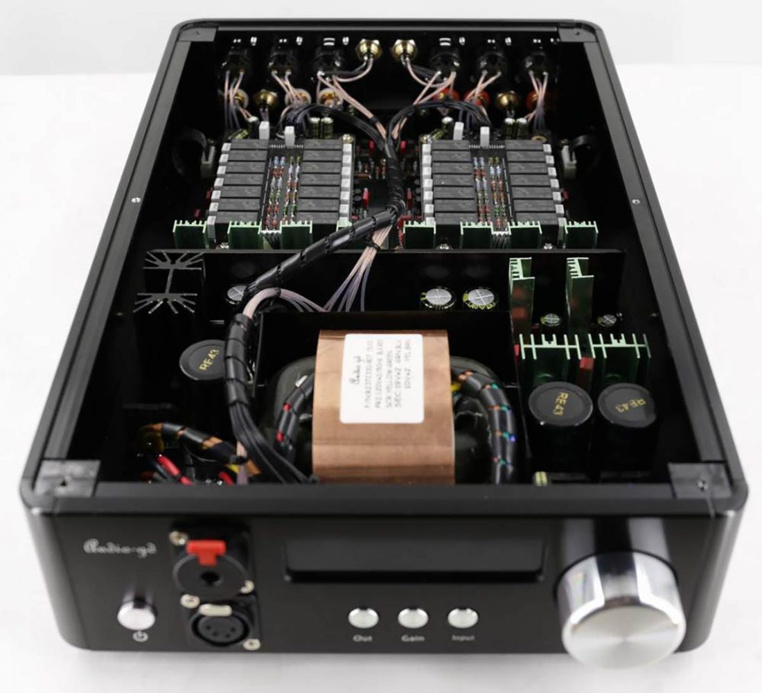
The doubling of devices in a push-pull amplifier increases the power and efficiency over single-ended operation at the cost of extra complexity. The added device(s) will also each contribute some amount of noise and output impedance—when you double the lumberjacks you double the potential for human error—but managing other aspects of the design mitigates these undesirables. In terms of harmonic distortion, the push-pull amplifier structure intrinsically cancels even-harmonic distortion, leaving just the odd-harmonics (which some label as subjectively ‘cold’ or ‘clinical’ in tone). Overall total harmonic distortion (THD) is generally lower for push-pull than for single-ended, though the composition of the distortion harmonics differs. The Audio-gd NFB-1AMP (as well as several other Audio-gd amplifiers) uses a variation of a popular push-pull output stage known as the diamond buffer. This circuit is common to many transistor-based headphone amplifiers because of its low noise and distortion contributions and its low output impedance. You will also find diamond buffer output stages in amplifiers like the Lehmann Cube and the innards of integrated circuits (ICs) like the LME49600 used in the Neurochrome HP-1.
Amplifier Classes
Amplifier classes are not night school for aspirational little transistors and tubes (as adorable as that mental picture may be). The class an amplifier falls into tells us a lot about how much power the amplifier consumes under operation. For an amplifier to produce power into headphones, it must deliver both voltage and current. We usually think of voltages in terms of potentials and currents in terms of flows. The current flows in an amplifier have a large impact on efficiency and distortion, as well as several other key audio parameters.
Class A
The tubes or transistors in a Class A amplifier are always conducting current. This means that they must conduct enough current to accommodate the maximum power output at all signal levels, even at idle. As a result of this constant current flow, Class A amplification runs hot, leading to a larger chassis or heatsinks. Low power efficiency and a large size make Class A a difficult proposition in portable applications. So if Class A is so inferior in efficiency and size, why would anyone put up with it? Well, tubes’ and transistors’ amplification varies with the amount of current flowing through them. The variation of amplification with signal creates distortion. So, the higher and more consistent current flow in Class A generally leads to more linear (lower distortion) performance from the amplifying devices.
Class B
Whereas the devices in a Class A circuit are always conducting at the maximum current needed for full output, the devices in a Class B circuit switch off where possible in order to increase efficiency. By nature, Class B circuits will use pairs of transistors or tubes in a push-pull arrangement. While one in the pair conducts, the other switches off. This is hugely more efficient than Class A, but you’ll probably never find a Class B audio amplifier. We rarely ever see high-fidelity Class B amplification because of something called crossover distortion. Remember how we said that devices’ amplification changes with current flow and that this creates distortion? Crossover distortion is created by the amplifying devices switching on and off as the output ‘crosses over’ from one device in a pair to the other. This is a significant source of distortion; luckily engineers have come up with a good compromise solution.
Class AB
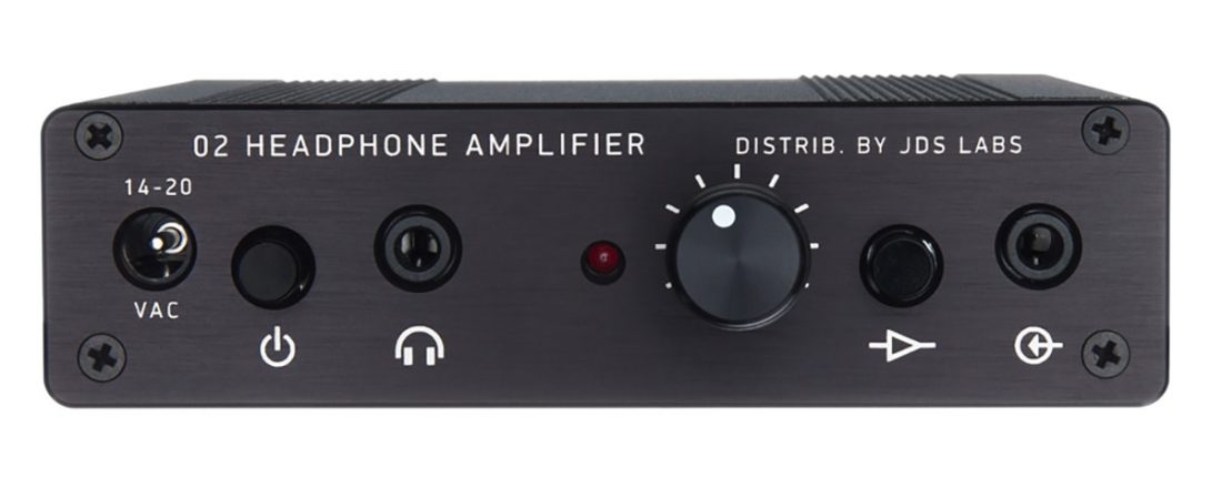
A Class AB amplifier always has some current flowing in it but that current is much less than what’s required by the maximum output. This makes Class AB amplification much more power efficient than Class A amplification and also allows it to be more compact because it generates less heat. Compact and portable amplifiers typically use Class AB amplification to maximize battery life and minimize the footprint. The Objective 2 made under various brands is an example of a Class AB battery-powered amplifier. The standard design advertises a 7-9 hour battery life from its pair of standard 9V cells. This improves to 20-30 hours in a low power version. Most versions of the amp include an DC (wall) power supply for charging and desktop operation. Unlike the on and off switching in Class B, a Class AB design maintains a minimum current flow in the amplifiers at all times. This greatly reduces crossover distortion created by devices switching on and off. Up to a certain power level, Class AB amplifiers operate completely in Class A with both output devices conducting equal current. Beyond this usually modest level, the amp will deliver higher power by operating in Class AB. The THX AAA series of amplifiers from manufacturers like Massdrop or Monoprice are desktop Class AB designs. While there’s some additional wizardry at work to reduce distortion, these amplifiers operate in Class AB as a compromise between efficiency and maximum output power.
Class C-Z
There are many other classes of amplification, but in the grand scheme of things, headphones are pretty low-power devices. Exotic amplification strategies like the switching power rails of Class G or pulse width modulation of Class D are not generally employed or needed to power headphones.
Output Coupling
How our circuit connects to our headphones also plays a role in the performance and overall sonic character of an amplifier. No, we’re not talking about what precious metal your cable is made of or how many rhodium crystals adorn the headphone jack. We’re referring to the coupling, or how the signal is interfaced, between the amp and headphone load.
Direct
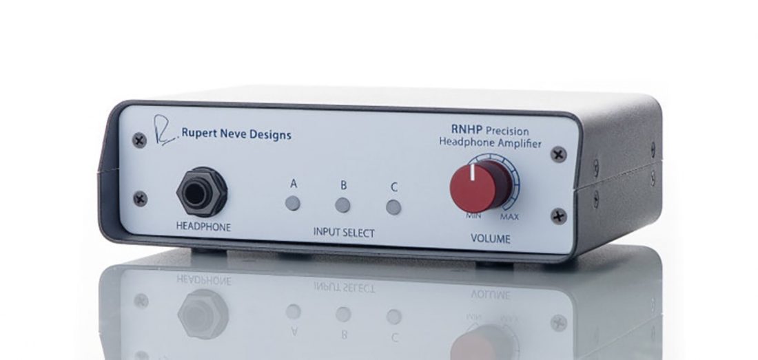
Direct coupling is exactly what it sounds like. The amplifier has nothing but wire between it and the headphones. While this is undoubtedly the purist connection, it doesn’t come without some caveats. Any net DC voltage on the output of the amplifier appears across the headphones; this is known as DC offset. While it would take a fairly catastrophic amount of DC offset to overheat and damage a pair of headphones, the unwanted DC voltage displaces the headphone driver from its natural centered position. This means it cannot move as far in one direction as the other, reducing the maximum dynamic range and potentially introducing unwanted distortion. None of the above stops designers from direct coupling the output of an amplifier when they can. Many employ extra protection systems that disconnect the output at power up and power down (when offset issues are most prevalent) or if the amplifier detects a problem. These protection circuits add complication though and complication is a source of both potential failure and costs. For that reason, other “less pure” methods of coupling are still popular. The Rupert Neve Designs RNHP was developed by a legend in the studio and production industry. To this day, Neve consoles are highly sought-after pieces of studio equipment (see the great Dave Grohl documentary ‘Sound City’). Based on circuits in much pricier equipment, the RNHP headphone amp has direct-coupled outputs with near zero output impedance.
Capacitors
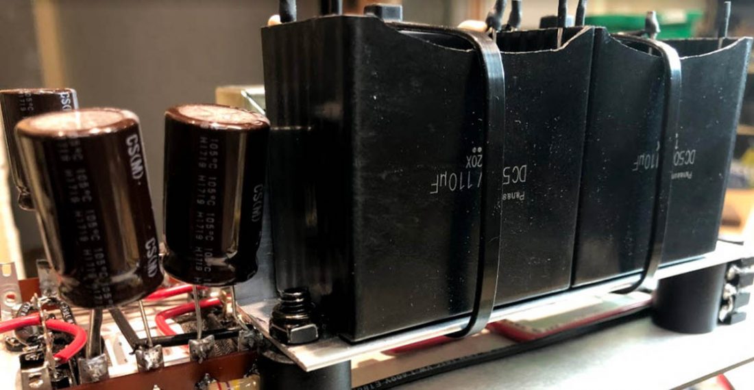
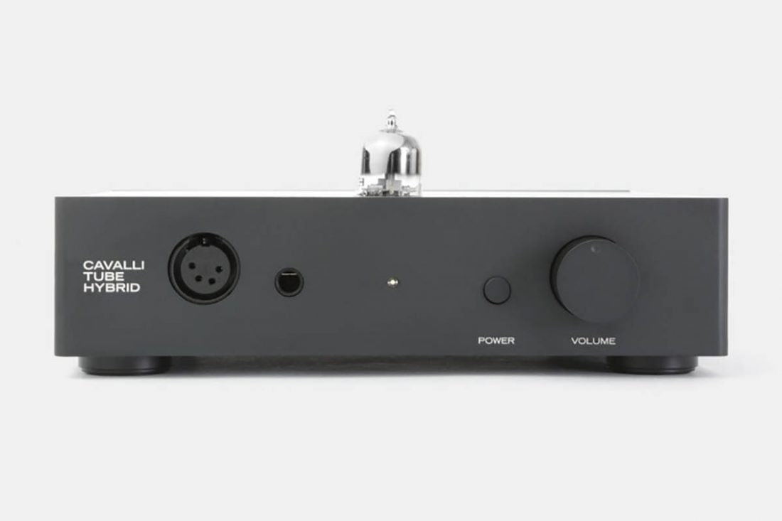
An output capacitor provides a simple solution to potential DC offset issues. Capacitors, one of the fundamental circuit components, pass audio signals (alternating current or AC) but not direct current (DC) voltages. Because they are a common component, capacitors also tend to be rather inexpensive (notwithstanding boutique audiophile types). These factors make cap-coupling a common practice in headphone amplifiers. Of course, no coupling type comes without some stipulation. Although the ideal capacitor is completely transparent on paper, real-world capacitors, materials, and manufacturing techniques can introduce some coloring of the sound. The most common objection is in low-frequency behavior where an improperly sized or chosen capacitor can introduce distortion and/or low frequency roll-off. Competent designers work around this, but it is a well-documented phenomenon nonetheless. The Drop x Cavalli Tube Hybrid (CTH), a collaboration with well-known audio designer Alex Cavalli, uses capacitor coupling on its output. Although Cavalli’s original design was direct-coupled, the change to cap-coupling for the Massdrop amp was likely motivated by both simplicity (ie less to go wrong) and cost. By the way, the original CTH used a variation of the diamond buffer referred to earlier in the article.
Transformers
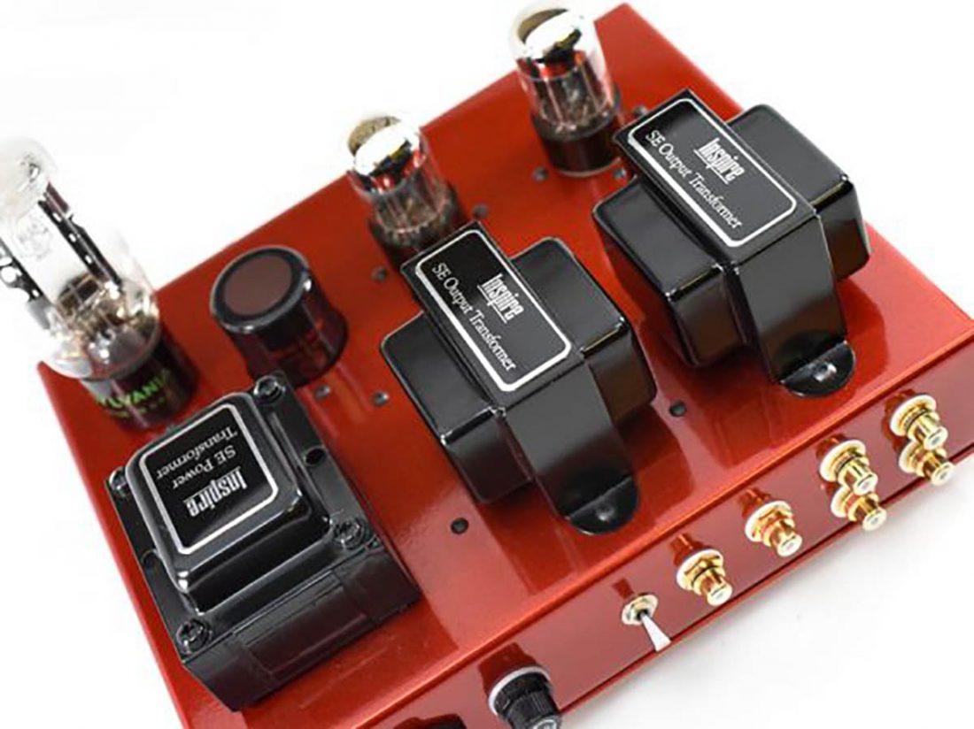
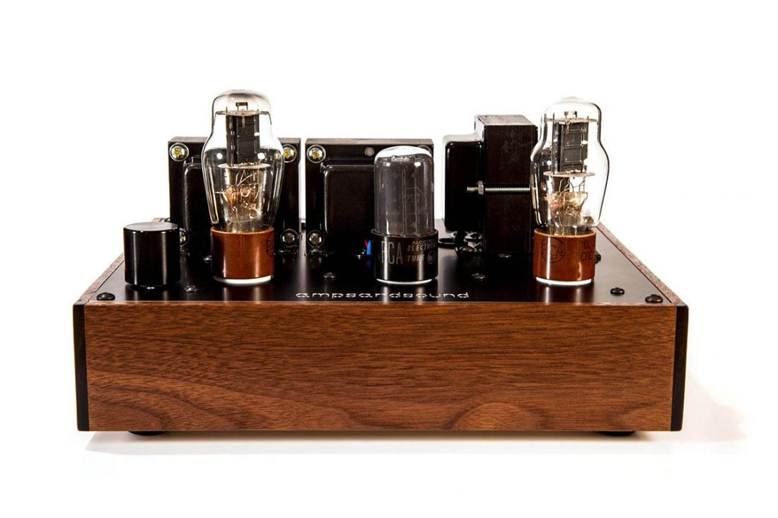
Transformers are an alternative form of output coupling that, like capacitors, block DC voltage and pass AC signals. Transformers have an important additional feature though: they transform impedance. You are probably familiar with impedance as a rating or specification for your headphones. In the case of a tube amplifier (which is where one usually sees output transformers), the relatively low impedance of the headphone is transformed into a much higher impedance for the tube. Transformers, by nature, output a balanced signal. This makes configuring a transformer-coupled tube amplifier to drive balanced connection headphones simple for the designer. The Dragon Inspire IHA-1 is a transformer-coupled tube amplifier sporting both unbalanced and balanced outputs. Transformers are large, heavy, and expensive. They also have their own set of bandwidth challenges at both frequency extremes. In fact, the phrase ‘tube sound’ when used to denote a softer top end and mid-centric presentation probably has more to do with transformers than it does with tubes. Good quality transformers and proper design eliminates treble or bass roll-off but they aren’t cheap. Output Transformerless (OTL) amplification side-steps some of the frequency-related transformer challenges. OTL means simply that the amp does not use transformers. Amplifiers advertised as OTL are usually cap-coupled and must still deal with the effects of a low impedance load on tubes, so OTL is a trade-off, not a silver bullet. The Bottlehead Crack mentioned earlier is an example of OTL amplification. The Amps and Sound Kenzie is single-ended transformer-coupled tube amplifier. Its output transformers feature multiple taps to accommodate different headphone impedance loads. This provides the tubes with a consistent impedance despite drastically different headphone ratings. Keeping the impedance loading on the tubes more consistent relaxes some of the transformer requirements and generally makes the amp’s sound more predictable into a wider variety of headphones.
Amplifying Devices
Here’s where the author infuriates every reader, no matter their allegiance. There is no greater debate in audio amplification than tubes vs transistors vs opamps. If you’ve been reading along though, you have noticed that amplifiers are not defined by any single design decision. They are the strategic culmination of many variables.
Tubes
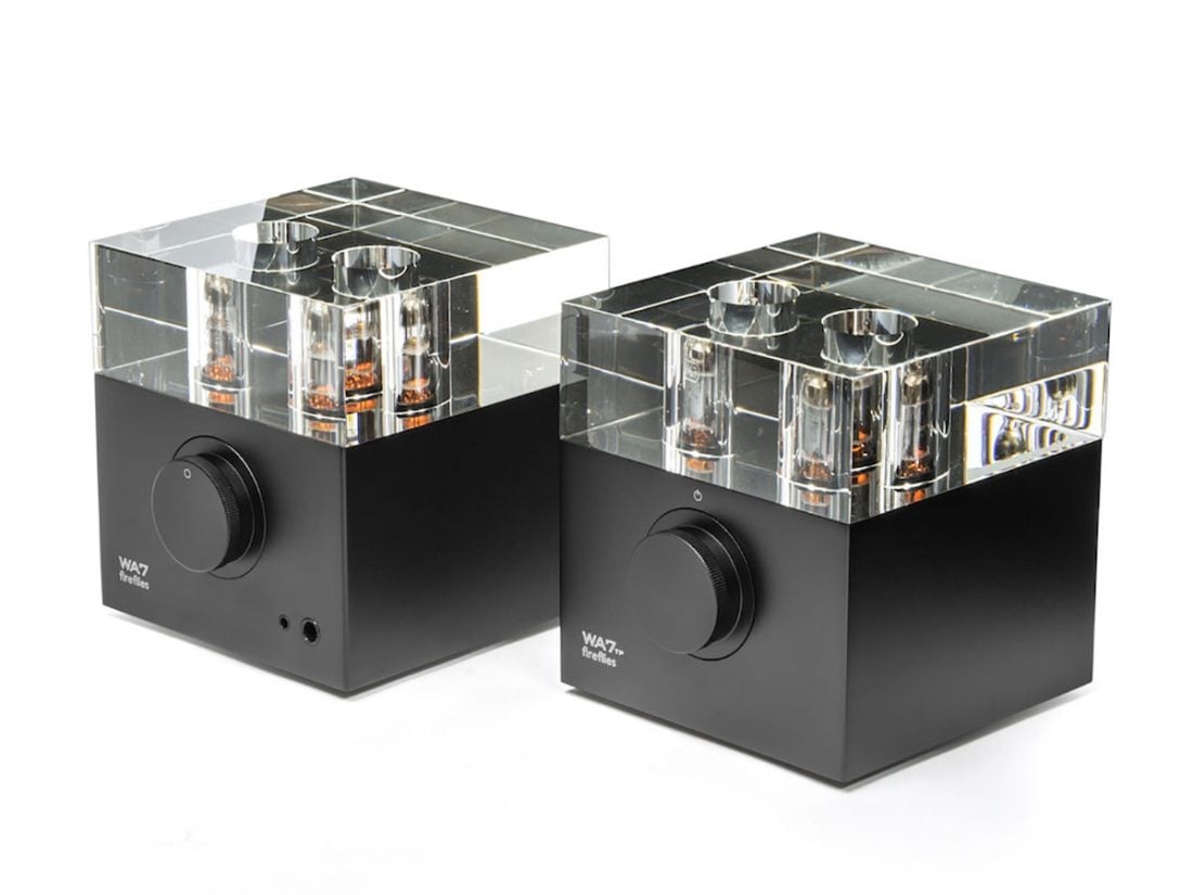
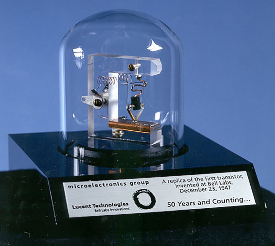
Vacuum tubes are the OG amplification device. They’ve been used in everything from hearing aids to tanks. Despite their age and seeming obsolescence, tube audio persists in both the musical instruments market (guitar amps, studio gear) and the high fidelity audio market. On a device-to-device basis, tubes are lower distortion devices than transistors (note that this isn’t saying tube amps are lower distortion than transistor amps). What distortion tubes do produce tends to be concentrated in low-order monotonically decaying harmonics (there’s that phrase again). That is to say, that tube distortion is considered unobjectionable by many listeners. Tube designs tend towards minimalist implementations because of these innate characteristics. Tubes are at home in high voltage environments. High voltage parts are more expensive and the voltages themselves are potentially dangerous if you go poking around the insides of a live amplifier. High impedance loads (600 ohm headphones, electrostatic headphones) require higher voltage to produce considerable power. Producing high voltage usually requires an on-board power supply rather than a wall wart, making tube amplifiers larger and more expensive. Tubes look cool. On one hand, this has nothing to do with the sound produced. On the other hand, it may have something to do with the listener’s enjoyment of the musical experience. The Woo Audio WA7 is a Class A, single-ended, transformer-coupled tube amplifier (I hope that string of terms has started to mean something by now). It bucks the minimalist trend by including a USB Digital-to-Analog Converter (DAC), but the tube amplification circuit is very simple at its core. A separate power supply chassis of about the same size as the amplifier itself is available as an option.
Transistors
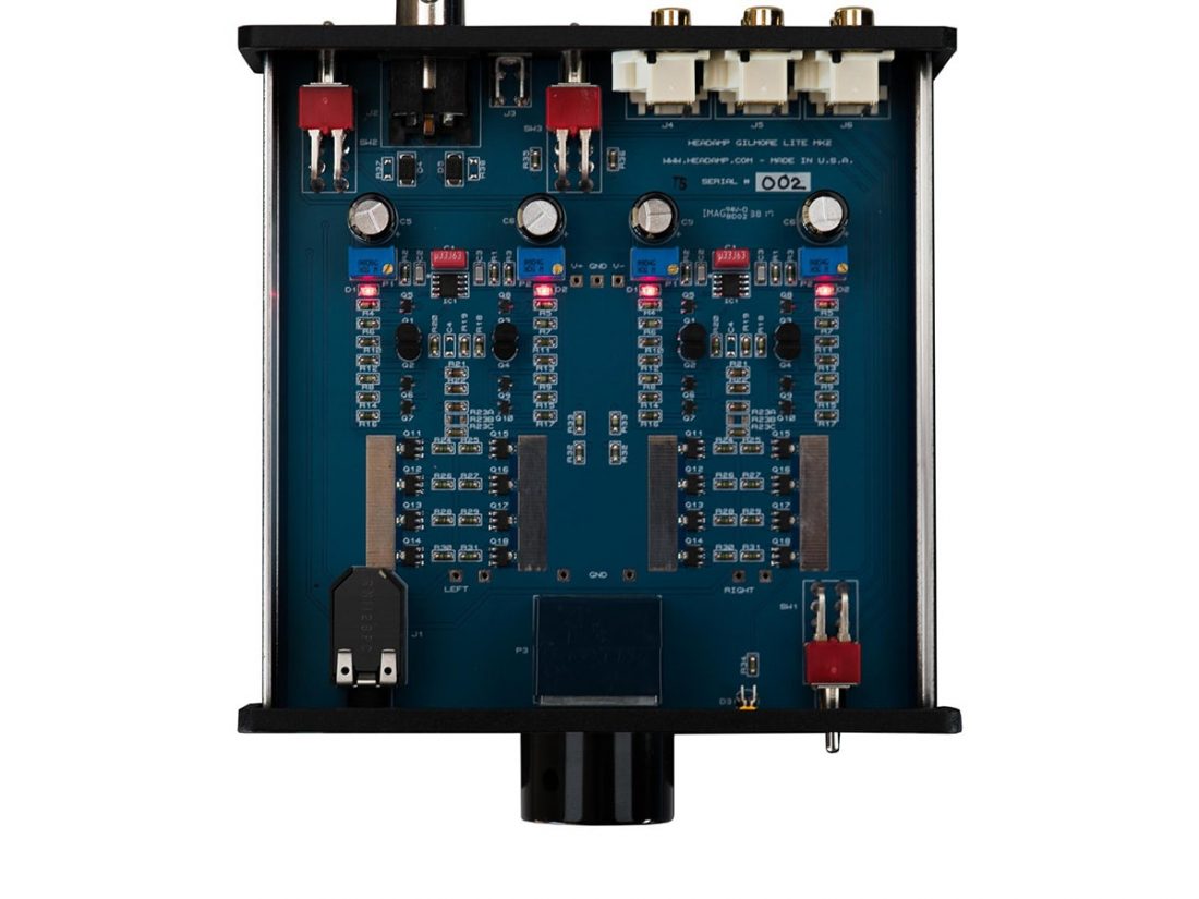
Whereas high impedance headphones benefit from high voltage, low impedance headphones benefit from healthy current. This is a key area where transistors have a large advantage over tubes (which otherwise require a transformer to drive a low impedance). The higher the current, the more heat becomes a potential issue, but heatsinks or Class AB operation are solutions to this issue. Tubes come in one electrical flavor that we’ll call peanut butter (N-channel). Peanut butter to peanut butter connections work, but they become awkward. Transistors come in two flavors: peanut butter and jelly (N-channel and P-channel). The extra flavor makes direct connections between transistors much easier. This, in turn, makes higher gain possible, which is important for negative feedback (next section). Lastly, transistors dominate today’s electronics because they are compact and (relative to tubes) inexpensive. This plays a huge role in giving us high quality portable audio and in making high fidelity audio more accessible to more people. More music in more places for more people. That’s a darn good legacy. The HeadAmp Gilmore Lite Mk2 is a Class A transistor amplifier based on designs by Kevin Gilmore, a well-known headphone amp designer. It uses Junction Field Effect Transistors (JFETs) at the input and Bipolar Junction Transistors (BJTs) on the output in a push-pull configuration. Based on other publicly available designs by Gilmore, the HeadAmp Gilmore Lite Mk2 is direct-coupled from input through to output.
Opamps and Integrated Circuits
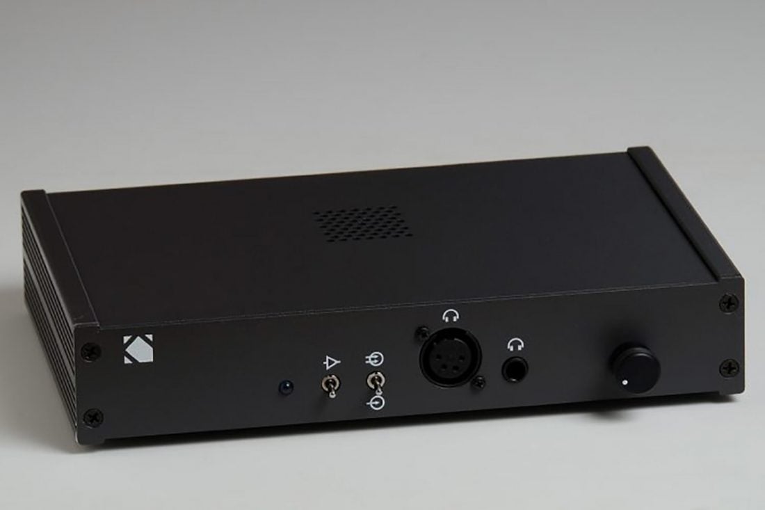
You might say that operational amplifiers (casually referred to as opamps) are the natural evolution of transistors for the audio products market. Opamps are integrated circuits (ICs), meaning they are not a single device like a hammer or a screwdriver, but a collection of devices for a specialized purpose, like an impact driver. You might think this feat of engineering makes opamps expensive, but you’d (mostly) be wrong. Mass-production, miniaturization, and countless R&D hours optimizing opamp performance make them cheap, compact, and very power efficient. There are some pricey exceptions (looking at you BUF634), but for the most part high performance opamps end up rather affordable once they’ve been adopted by manufacturers. Mass production and universal application, however, cuts both ways when it comes to opamps. Although opamps are highly optimized for their application (amplifying without distortion), they have limited configurations and somewhat standardized operating conditions. Amplifier manufacturers seeking unique designs or specialized applications (electrostatic headphone amplifiers, for example) may focus on discrete circuits, or individual transistors, rather than ICs. The Neurochrome HP-1 is, in many ways, the ultimate expression of what opamps can do for headphone amplification. It is compact, extremely low distortion, and totally polarizing in many audio circles. Is colorless, odorless, tasteless amplification the path to ultimate enlightenment or merciless oblivion? You’ll have to wait for Tom Christiansen’s next headphone amp to come out because the HP-1 is no longer being produced (you can keep tabs at his newsletter here).
Hybrids
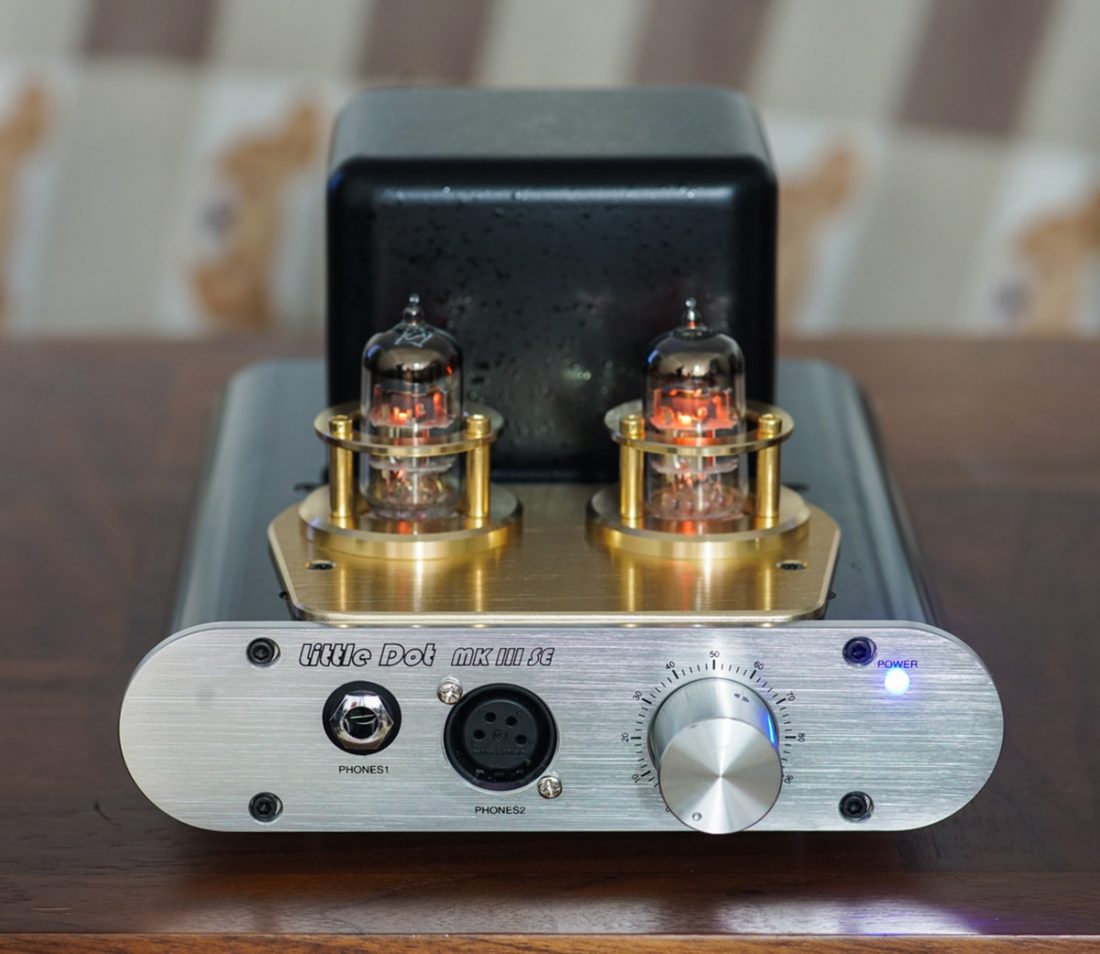
Beyond strict transistors, tubes, or opamps, amplifier designers may employ any combination of these devices. While any mix could probably be called a hybrid amplifier, we usually reserve that term for anything built with both tubes and transistors or opamps. As mentioned earlier in this article, tubes are more linear voltage amplification devices while transistors have a significant advantage handling the current demanded by low impedance headphones. Hybrids generally seek to exploit the strengths of both types of device while minimizing the weaknesses. There are many potential strategies but hybrid amplifiers generally use a tube to amplify the input signal and transistors or opamps to drive the headphones. The Little Dot Mk III SE is a well-known hybrid amplifier using both tubes and a discrete Class A transistor output stage. While it’s priced higher than typical opamp-based amplifiers, it’s also much more affordable than most exclusively tube-based amplifiers. Plus it has bits of glowing glass on top, so it has that going for it which is nice.
Negative Feedback
You may have noticed how carefully chosen the wording was about tubes, transistors, and linearity in the last section. Extrapolating the performance of an amplifier from the characteristics of any one device making it up is an exercise in futility; it’s the amplifier as a whole that matters. Negative feedback is an important circuit detail to consider in the big picture. Negative feedback is a technique that feeds ‘errors’ of an amplifier (ie distortion) back through the circuit, resulting in their cancellation. All that’s required is some gain to spare (which is why direct coupling with transistors comes in handy). Not only does negative feedback reduce distortion, it also lowers output impedance, making the amplifier less sensitive to the impedance variations with frequency that most headphones exhibit. If this all sounds too good to be true, that’s because it basically is. While negative feedback does lower distortion, at low levels (under about 20db) it increases upper harmonic distortion which is more audible to human listeners. So, amplifiers using negative feedback must start with low distortion (making negative feedback somewhat superfluous) and/or apply very large amounts of feedback (requiring large amounts of gain) in order to see the distortion advantages. In addition to negative feedback, THX Achromatic Audio Amplifier (AAA™) designs like the Benchmark HPA4 use something called feed-forward error correction. Rather than just feed the amplifier’s output errors back to be cancelled, the HPA4 also feeds errors created early in the amplification process directly to the output to be corrected. The combination of error-correction strategies makes it a very low distortion amplifier that is highly stable into any kind of headphone load.
Conclusion
We’re participating in a niche and highly-technical hobby that tends to obsess over details and debate abstractions. Naturally, this can lead to engineering hearsay and misunderstanding of some of the finer points. When much of the pre-purchase research takes place online and in social media instead of in a showroom (where you can use your own ears), this can be incredibly frustrating. I hope this primer provides a wider vocabulary and a better understanding of some of the often-promoted but seldom-explained concepts and methods common to headphone amplification. At the very least, you should now be able to read the Technical Details section for any amplifier and make an educated guess as to the sonic fingerprints left by the engineer’s design philosophy.
